

Diesel EngineInLocomotive
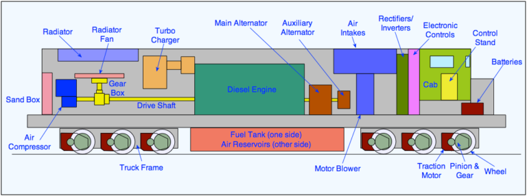
The modern diesel locomotive is a self contained version of the electric locomotive. Like the electric locomotive, it has electric drive, in the form of traction motors driving the axles and controlled with electronic controls. It also has many of the same auxiliary systems for cooling, lighting, heating, braking and hotel power (if required) for the train. It can operate over the same routes (usually) and can be operated by the same drivers. It differs principally in that it carries its own generating station around with it, instead of being connected to a remote generating station through overhead wires or a third rail. The generating station consists of a large diesel engine coupled to an alternator producing the necessary electricity. A fuel tank is also essential. It is interesting to note that the modern diesel locomotive produces about 35% of the power of a electric locomotive of similar weight.
Diesel-Electric Types
Diesel-electric locomotives come in three varieties, according to the period in which they were designed. These three are:
DC – DC (DC generator supplying DC traction motors)
AC – DC (AC alternator output rectified to supply DC motors)
AC – DC – AC (AC alternator output rectified to DC and then inverted to 3-phase AC for the traction motors).
There is one traction alternator (or generator) per diesel engine in a locomotive (standard North American practice anyway). The Alco C628 was the last locomotive to lead the horsepower race with a DC traction alternato
The output from the main alternator is AC but it can be used in a locomotive with either DC or AC traction motors. DC motors were the traditional type used for many years but, in the last 10 years, AC motors have become standard for new locomotives. They are cheaper to build and cost less to maintain and, with electronic management can be very finely controlled. To see more on the difference between DC and AC traction technology try the Electronic Power Page on this site.
To convert the AC output from the main alternator to DC, rectifiers are required. If the motors are DC, the output from the rectifiers is used directly. If the motors are AC, the DC output from the rectifiers is converted to 3-phase AC for the traction motors.
In the US, there are some variations in how the inverters are configured. GM EMD relies on one inverter per truck, while GE uses one inverter per axle – both systems have their merits. EMD’s system links the axles within each truck in parallel, ensuring wheel slip control is maximised among the axles equally. Parallel control also means even wheel wear even between axles. However, if one inverter (i.e. one truck) fails then the unit is only able to produce 50 per cent of its tractive effort. One inverter per axle is more complicated, but the GE view is that individual axle control can provide the best tractive effort. If an inverter fails, the tractive effort for that axle is lost, but full tractive effort is still available through the other five inverters. By controlling each axle individually, keeping wheel diameters closely matched for optimum performance is no longer necessary. This paragraph sourced from e-mail by unknown correspondent 3 November 1997.
The amount of power obtained from a cylinder in a diesel engine depends on how much fuel can be burnt in it. The amount of fuel which can be burnt depends on the amount of air available in the cylinder. So, if you can get more air into the cylinder, more fuel will be burnt and you will get more power out of your ignition. Turbo charging is used to increase the amount of air pushed into each cylinder. The turbocharger is driven by exhaust gas from the engine. This gas drives a fan which, in turn, drives a small compressor which pushes the additional air into the cylinder. Turbocharging gives a 50% increase in engine power.
The main advantage of the turbocharger is that it gives more power with no increase in fuel costs because it uses exhaust gas as drive power. It does need additional maintenance, however, so there are some type of lower power locomotives which are built without it.
Hydraulic transmission works on the same principal as the fluid coupling but it allows a wider range of “slip” between the engine and wheels. It is known as a “torque converter”. When the train speed has increased sufficiently to match the engine speed, the fluid is drained out of the torque converter so that the engine is virtually coupled directly to the locomotive wheels. It is virtually direct because the coupling is usually a fluid coupling, to give some “slip”. Higher speed locomotives use two or three torque converters in a sequence similar to gear changing in a mechanical transmission and some have used a combination of torque converters and gears.
Some designs of diesel-hydraulic locomotives had two diesel engines and two transmission systems, one for each bogie. The design was poplar in Germany (the V200 series of locomotives, for example) in the 1950s and was imported into parts of the UK in the 1960s. However, it did not work well in heavy or express locomotive designs and has largely been replaced by diesel-electric transmission.
Wheels slip is the bane of the driver trying to get a train away smoothly. The tenuous contact between steel wheel and steel rail is one of the weakest parts of the railway system. Traditionally, the only cure has been a combination of the skill of the driver and the selective use of sand to improve the adhesion. Today, modern electronic control has produced a very effective answer to this age old problem. The system is called creep control.
Extensive research into wheel slip showed that, even after a wheelset starts to slip, there is still a considerable amount of useable adhesion available for traction. The adhesion is available up to a peak, when it will rapidly fall away to an uncontrolled spin. Monitoring the early stages of slip can be used to adjust the power being applied to the wheels so that the adhesion is kept within the limits of the “creep” towards the peak level before the uncontrolled spin sets in.
The slip is measured by detecting the locomotive speed by Doppler radar (instead of the usual method using the rotating wheels) and comparing it to the motor current to see if the wheel rotation matches the ground speed. If there is a disparity between the two, the motor current is adjusted to keep the slip within the “creep” range and keep the tractive effort at the maximum level possible under the creep conditions.
The diesel engines used in DMUs work on exactly the same principles as those used in locomotives, except that the transmission is normally mechanical with some form of gear change system. DMU engines are smaller and several are used on a train, depending on the configuration. The diesel engine is often mounted under the car floor and on its side because of the restricted space available. Vibration being transmitted into the passenger saloon has always been a problem but some of the newer designs are very good in this respect.
There are some diesel-electric DMUs around and these normally have a separate engine compartment containing the engine and the generator or alternator.
The diesel engine was first patented by Dr Rudolf Diesel (1858-1913) in Germany in 1892 and he actually got a successful engine working by 1897. By 1913, when he died, his engine was in use on locomotives and he had set up a facility with Sulzer in Switzerland to manufacture them. His death was mysterious in that he simply disappeared from a ship taking him to London.
The diesel engine is a compression-ignition engine, as opposed to the petrol (or gasoline) engine, which is a spark-ignition engine. The spark ignition engine uses an electrical spark from a “spark plug” to ignite the fuel in the engine’s cylinders, whereas the fuel in the diesel engine’s cylinders is ignited by the heat caused by air being suddenly compressed in the cylinder. At this stage, the air gets compressed into an area 1/25th of its original volume. This would be expressed as a compression ratio of 25 to 1. A compression ratio of 16 to 1 will give an air pressure of 500 lbs/in² (35.5 bar) and will increase the air temperature to over 800°F (427°C).
The advantage of the diesel engine over the petrol engine is that it has a higher thermal capacity (it gets more work out of the fuel), the fuel is cheaper because it is less refined than petrol and it can do heavy work under extended periods of overload. It can however, in a high speed form, be sensitive to maintenance and noisy, which is why it is still not popular for passenger automobiles.
There are two types of diesel engine, the two-stroke engine and the four-stroke engine. As the names suggest, they differ in the number of movements of the piston required to complete each cycle of operation. The simplest is the two-stroke engine. It has no valves. The exhaust from the combustion and the air for the new stroke is drawn in through openings in the cylinder wall as the piston reaches the bottom of the downstroke. Compression and combustion occurs on the upstroke. As one might guess, there are twice as many revolutions for the two-stroke engine as for equivalent power in a four-stroke engine.
The four-stroke engine works as follows: Downstroke 1 – air intake, upstroke 1 – compression, downstroke 2 – power, upstroke 2 – exhaust. Valves are required for air intake and exhaust, usually two for each. In this respect it is more similar to the modern petrol engine than the 2-stroke design.
In the UK, both types of diesel engine were used but the 4-stroke became the standard. The UK Class 55 “Deltic” (not now in regular main line service) unusually had a two-stroke engine. In the US, the General Electric (GE) built locomotives have 4-stroke engines whereas General Motors (GM) always used 2-stroke engines until the introduction of their SD90MAC 6000 hp “H series” engine, which is a 4-stroke design.
The reason for using one type or the other is really a question of preference. However, it can be said that the 2-stroke design is simpler than the 4-stroke but the 4-stroke engine is more fuel efficient.
Basically, the more power you need, the bigger the engine has to be. Early diesel engines were less than 100 horse power (hp) but today the US is building 6000 hp locomotives. For a UK locomotive of 3,300 hp (Class 58), each cylinder will produce about 200 hp, and a modern engine can double this if the engine is turbocharged.
The maximum rotational speed of the engine when producing full power will be about 1000 rpm (revolutions per minute) and the engine will idle at about 400 rpm. These relatively low speeds mean that the engine design is heavy, as opposed to a high speed, lightweight engine. However, the UK HST (High Speed Train, developed in the 1970s) engine has a speed of 1,500 rpm and this is regarded as high speed in the railway diesel engine category. The slow, heavy engine used in railway locomotives will give low maintenance requirements and an extended life.
There is a limit to the size of the engine which can be accommodated within the railway loading gauge, so the power of a single locomotive is limited. Where additional power is required, it has become usual to add locomotives. In the US, where freight trains run into tens of thousands of tons weight, four locomotives at the head of a train are common and several additional ones in the middle or at the end are not unusual.
Diesel engines can be designed with the cylinders “in-line”, “double banked” or in a “V”. The double banked engine has two rows of cylinders in line. Most diesel locomotives now have V form engines. This means that the cylinders are split into two sets, with half forming one side of the V. A V8 engine has 4 cylinders set at an angle forming one side of the V with the other set of four forming the other side. The crankshaft, providing the drive, is at the base of the V. The V12 was a popular design used in the UK. In the US, V16 is usual for freight locomotives and there are some designs with V20 engines.
Engines used for DMU (diesel multiple unit) trains in the UK are often mounted under the floor of the passenger cars. This restricts the design to in-line engines, which have to be mounted on their side to fit in the restricted space.
An unusual engine design was the UK 3,300 hp Class 55 locomotive, which had the cylinders arranged in three sets of opposed Vs in a triangle, in the form of an upturned delta, hence the name “Deltic”.
Before going too much further, we need to understand the definitions of tractive effort, drawbar pull and power. The definition of tractive effort (TE) is simply the force exerted at the wheel rim of the locomotive and is usually expressed in pounds (lbs) or kilo Newtons (kN). By the time the tractive effort is transmitted to the coupling between the locomotive and the train, the drawbar pull, as it is called will have reduced because of the friction of the mechanical parts of the drive and some wind resistance.
Power is expressed as horsepower (hp) or kilo Watts (kW) and is actually a rate of doing work. A unit of horsepower is defined as the work involved by a horse lifting 33,000 lbs one foot in one minute. In the metric system it is calculated as the power (Watts) needed when one Newton of force is moved one metre in one second. The formula is P = (F*d)/t where P is power, F is force, d is distance and t is time. One horsepower equals 746 Watts.
The relationship between power and drawbar pull is that a low speed and a high drawbar pull can produce the same power as high speed and low drawbar pull. If you need to increase higher tractive effort and high speed, you need to increase the power. To get the variations needed by a locomotive to operate on the railway, you need to have a suitable means of transmission between the diesel engine and the wheels.
One thing worth remembering is that the power produced by the diesel engine is not all available for traction. In a 2,580 hp diesel electric locomotive, some 450 hp is lost to on-board equipment like blowers, radiator fans, air compressors and “hotel power” for the train.
A diesel engine is started (like an automobile) by turning over the crankshaft until the cylinders “fire” or begin combustion. The starting can be done electrically or pneumatically. Pneumatic starting was used for some engines. Compressed air was pumped into the cylinders of the engine until it gained sufficient speed to allow ignition, then fuel was applied to fire the engine. The compressed air was supplied by a small auxiliary engine or by high pressure air cylinders carried by the locomotive.
Electric starting is now standard. It works the same way as for an automobile, with batteries providing the power to turn a starter motor which turns over the main engine. In older locomotives fitted with DC generators instead of AC alternators, the generator was used as a starter motor by applying battery power to it.
In an petrol engine, the power is controlled by the amount of fuel/air mixture applied to the cylinder. The mixture is mixed outside the cylinder and then applied by a throttle valve. In a diesel engine the amount of air applied to the cylinder is constant so power is regulated by varying the fuel input. The fine spray of fuel injected into each cylinder has to be regulated to achieve the amount of power required. Regulation is achieved by varying the fuel sent by the fuel pumps to the injectors.
The amount of fuel being applied to the cylinders is varied by altering the effective delivery rate of the piston in the injector pumps. Each injector has its own pump, operated by an engine-driven cam, and the pumps are aligned in a row so that they can all be adjusted together. The adjustment is done by a toothed rack (called the “fuel rack”) acting on a toothed section of the pump mechanism. As the fuel rack moves, so the toothed section of the pump rotates and provides a drive to move the pump piston round inside the pump. Moving the piston round, alters the size of the channel available inside the pump for fuel to pass through to the injector delivery pipe.
The fuel rack can be moved either by the driver operating the power controller in the cab or by the governor. If the driver asks for more power, the control rod moves the fuel rack to set the pump pistons to allow more fuel to the injectors. The engine will increase power and the governor will monitor engine speed to ensure it does not go above the predetermined limit. The limits are fixed by springs (not shown) limiting the weight movement.
The diesel engine in a diesel-electric locomotive provides the drive for the main alternator which, in turn, provides the power required for the traction motors. We can see from this therefore, that the power required from the diesel engine is related to the power required by the motors. So, if we want more power from the motors, we must get more current from the alternator so the engine needs to run faster to generate it. Therefore, to get the optimum performance from the locomotive, we must link the control of the diesel engine to the power demands being made on the alternator.
In the days of generators, a complex electro-mechanical system was developed to achieve the feedback required to regulate engine speed according to generator demand. The core of the system was a load regulator, basically a variable resistor which was used to very the excitation of the generator so that its output matched engine speed. The control sequence (simplified) was as follows:
- 1. Driver moves the power controller to the full power position
- 2. An air operated piston actuated by the controller moves a lever, which closes a switch to supply a low voltage to the load regulator motor.
- 3. The load regulator motor moves the variable resistor to increase the main generator field strength and therefore its output.
- 4. The load on the engine increases so its speed falls and the governor detects the reduced speed.
- 5. The governor weights drop and cause the fuel rack servo system to actuate.
- 6. The fuel rack moves to increase the fuel supplied to the injectors and therefore the power from the engine.
- 7. The lever (mentioned in 2 above) is used to reduce the pressure of the governor spring.
- 8. When the engine has responded to the new control and governor settings, it and the generator will be producing more power.
On locomotives with an alternator, the load regulation is done electronically. Engine speed is measured like modern speedometers, by counting the frequency of the gear teeth driven by the engine, in this case, the starter motor gearwheel. Electrical control of the fuel injection is another improvement now adopted for modern engines. Overheating can be controlled by electronic monitoring of coolant temperature and regulating the engine power accordingly. Oil pressure can be monitored and used to regulate the engine power in a similar way.
Like an automobile engine, the diesel engine needs to work at an optimum temperature for best efficiency. When it starts, it is too cold and, when working, it must not be allowed to get too hot. To keep the temperature stable, a cooling system is provided. This consists of a water-based coolant circulating around the engine block, the coolant being kept cool by passing it through a radiator.
The coolant is pumped round the cylinder block and the radiator by an electrically or belt driven pump. The temperature is monitored by a thermostat and this regulates the speed of the (electric or hydraulic) radiator fan motor to adjust the cooling rate. When starting the coolant isn’t circulated at all. After all, you want the temperature to rise as fast as possible when starting on a cold morning and this will not happen if you a blowing cold air into your radiator. Some radiators are provided with shutters to help regulate the temperature in cold conditions.
If the fan is driven by a belt or mechanical link, it is driven through a fluid coupling to ensure that no damage is caused by sudden changes in engine speed. The fan works the same way as in an automobile, the air blown by the fan being used to cool the water in the radiator. Some engines have fans with an electrically or hydrostatically driven motor. An hydraulic motor uses oil under pressure which has to be contained in a special reservoir and pumped to the motor. It has the advantage of providing an in-built fluid coupling.
A problem with engine cooling is cold weather. Water freezes at 0°C or 32°F and frozen cooling water will quickly split a pipe or engine block due to the expansion of the water as it freezes. Some systems are “self draining” when the engine is stopped and most in Europe are designed to use a mixture of anti-freeze, with Gycol and some form of rust inhibitor. In the US, engines do not normally contain anti-freeze, although the new GM EMD “H” engines are designed to use it. Problems with leaks and seals and the expense of putting a 100 gallons (378.5 litres) of coolant into a 3,000 hp engine, means that engines in the US have traditionally operated without it. In cold weather, the engine is left running or the locomotive is kept warm by putting it into a heated building or by plugging in a shore supply. Another reason for keeping diesel engines running is that the constant heating and cooling caused by shutdowns and restarts, causes stresses in the block and pipes and tends to produce leaks.
Like an automobile engine, a diesel engine needs lubrication. In an arrangement similar to the engine cooling system, lubricating oil is distributed around the engine to the cylinders, crankshaft and other moving parts. There is a reservoir of oil, usually carried in the sump, which has to be kept topped up, and a pump to keep the oil circulating evenly around the engine. The oil gets heated by its passage around the engine and has to be kept cool, so it is passed through a radiator during its journey. The radiator is sometimes designed as a heat exchanger, where the oil passes through pipes encased in a water tank which is connected to the engine cooling system.
The oil has to be filtered to remove impurities and it has to be monitored for low pressure. If oil pressure falls to a level which could cause the engine to seize up, a “low oil pressure switch” will shut down the engine. There is also a high pressure relief valve, to drain off excess oil back to the sump.